Sensors are a vital part of any robotic project, as they allow a robot to get information about the environment in which it’s operating. Without sensors, a robot has no information about the world around it, and it’s very tough to program intelligent behaviours for the robot.
With sensors your robot can find out about the world
Now, you’ve always been able to attach sensors to our Raspberry Pi Camera Robot and the Arduino Mini Driver board we use for motor control, but previously you would have had to modify quite a bit of code in order to get your sensor data out. To fix this, we’ve just released an update to the software for our Raspberry Pi Camera robot which makes things much easier. You can now get a large number of sensors to work simply by connecting them to the Mini Driver. The new Mini Driver firmware repeatedly reads from the attached sensors and sends the readings up to the Pi at a rate of 100 times a second. Once on the Pi, the sensor values can be easily retrieved using the robot web server’s websocket interface. Sensors can also be connected directly to the Pi, with sensor readings returned in the same way.
In this tutorial we show you how to update your robot’s software if needed, how to connect sensors to robot, and then how to read the sensor values using the Python py_websockets_bot library. This will let you write control scripts for your robot that use sensors, and which either run on the Pi, or which run on another computer connected over the network.
Upgrading the Software
If you bought your robot before this post was published, then it’s likely that you’ll need to upgrade the software on your robot. Probably the easiest way to do this is to download the latest SD card image from here, and then flash it to an SD card using the instructions here. If you’re interested, you can also find details of how we built the image from the ground up here.
Moving the Neck Pan and Tilt Servo Connectors
Originally, the pan and tilt servo were connected up to pins D4 and D3 respectively. With this software update, we’ve had to move the servo connections in order to be able to attach wheel encoder sensors (these need the interrupts on D2 and D3). Therefore, in order to make sure that the neck motors keep on working, move the pan servo to the row marked D11, and the tilt servo to the row marked D6.
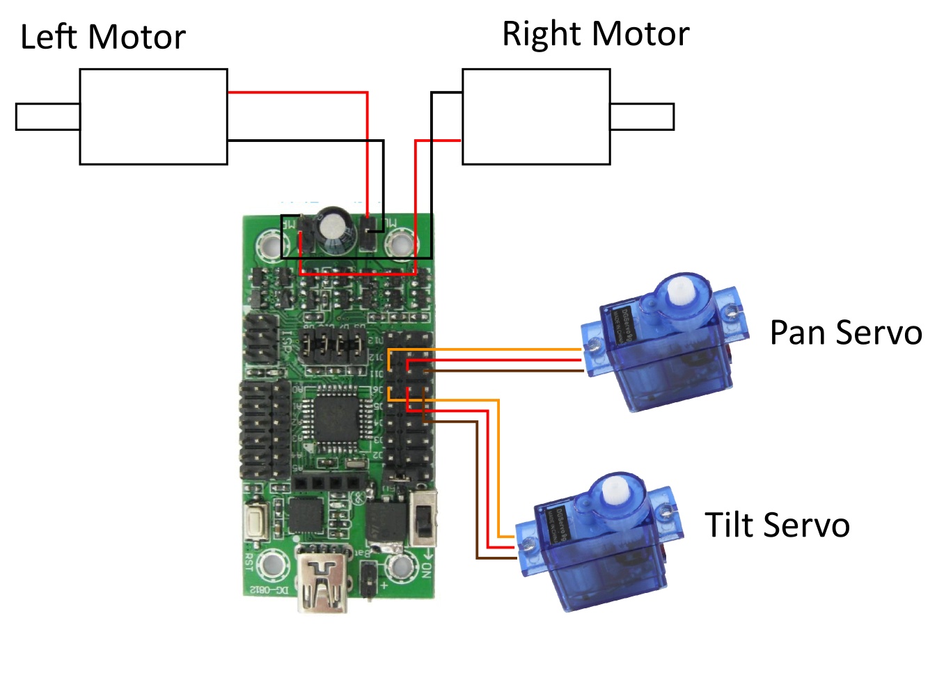
Move the neck servos to pins D6 and D11
Connecting Sensors to the Robot
You have two main options when connecting sensors to the robot. You can either connect sensors to the Mini Driver, or alternatively you can connect them to the Raspberry Pi.
Connecting sensors to the Mini Driver is usually the simpler option, as the Mini Driver can talk to sensors running at 5V, and the sensor values are read automatically at a rate of 100Hz by the firmware on the Mini Driver. It can be useful however, to sometimes connect sensors to the Raspberry Pi. This can happen if you run out of pins on the Mini Driver, or if you need to use I2C or SPI to communicate with a sensor (as these protocols aren’t supported in the Mini Driver firmware yet, and probably won’t be due to a lack of space). Connecting sensors to the Raspberry Pi will probably involve a bit more work as you may need to shift 5V sensor outputs to the 3.3V used by the Pi, and you’ll also need to write a little bit of Python code to talk to the sensor.
With that in mind, we’ll look at the two options for connecting the sensors in a bit more detail. Please Note: In the examples below we use sensors we sell in our store, but there’s nothing to stop you from using any other sensor that you can find, as long as they’re electrically compatible. This means that there’s a truly vast array of sensors out there that you can use with your robot. ![]()
Connecting Sensors to the Mini Driver
The range of sensors you can attach to the Mini Driver includes digital sensors, analog sensors, encoders and an ultrasonic sensor. The ability to read from analog sensors is really useful as the Raspberry Pi doesn’t have an Analog to Digital Converter (ADC) of its own.
The Mini Driver runs at 5V and so it’s assumed that that’s the voltage level at which sensors you connect to the Mini Driver will run at as well. Please check that the sensors you connect to the Mini Driver are happy running at 5V to avoid damaging them. Also, please check your 5V (VCC) and GND connections carefully before turning the power on, as getting them the wrong way round may let the magic smoke out of your sensors, rendering them useless…
Digital Inputs
Digital sensors are sensors which give a simple high or low output as a result of detecting something. There are 8 pins that you can attach digital sensors to, pins D12, D13 and the 6 analog pins A0 to A5. It may seem odd that you can attach digital sensors to the analog pins, but the pins can be used as both type of input. We’ll configure the exact type of input for the pins in software later on.
As an example of attaching digital sensors we use the trusty line sensor which gives a high signal when it detects a black line on a white background.
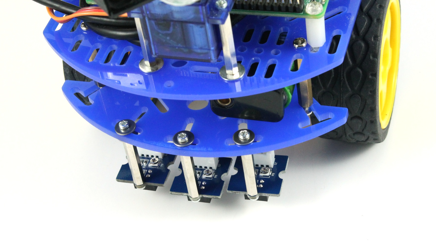
Multiple sensors allow you to detect the direction to the line
In the image above we’ve attached 3 line sensors to the front of the chassis using some M2 spacers, and we then connect them to the Mini Driver using some female jumper wires, as shown in the image below.
It doesn’t matter which of the 8 possible digital input pins you use, but we’ve used pins A1, A2 and A5, and will then configure these pins as digital inputs in software. With these 3 sensors attached it’s now possible to make the robot follow a black line laid down using a marker pen, or insulation tape.
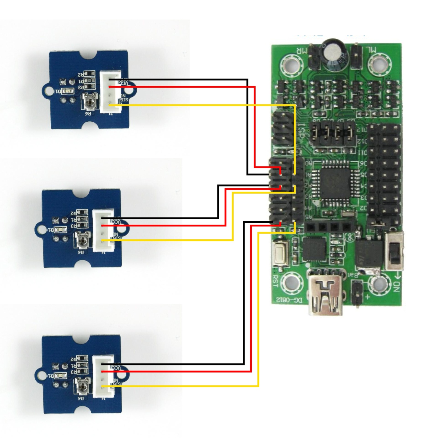
One possible way of attaching line sensors. Note: One of the pins on the line sensor is marked as NC (No connection) so the extra wire can be tied back or cut away.
Attaching an Ultrasonic Sensor
Ultrasonic sensors emit bursts of high pitched sound waves (beyond the range of human hearing) which bounce off obstacles in front of the robot. By measuring how long it takes for signals to go out and come back, the robot can work out if there are any obstacles in front of it, and if so, how far away they are.
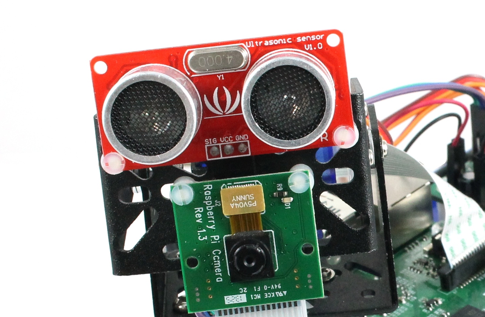
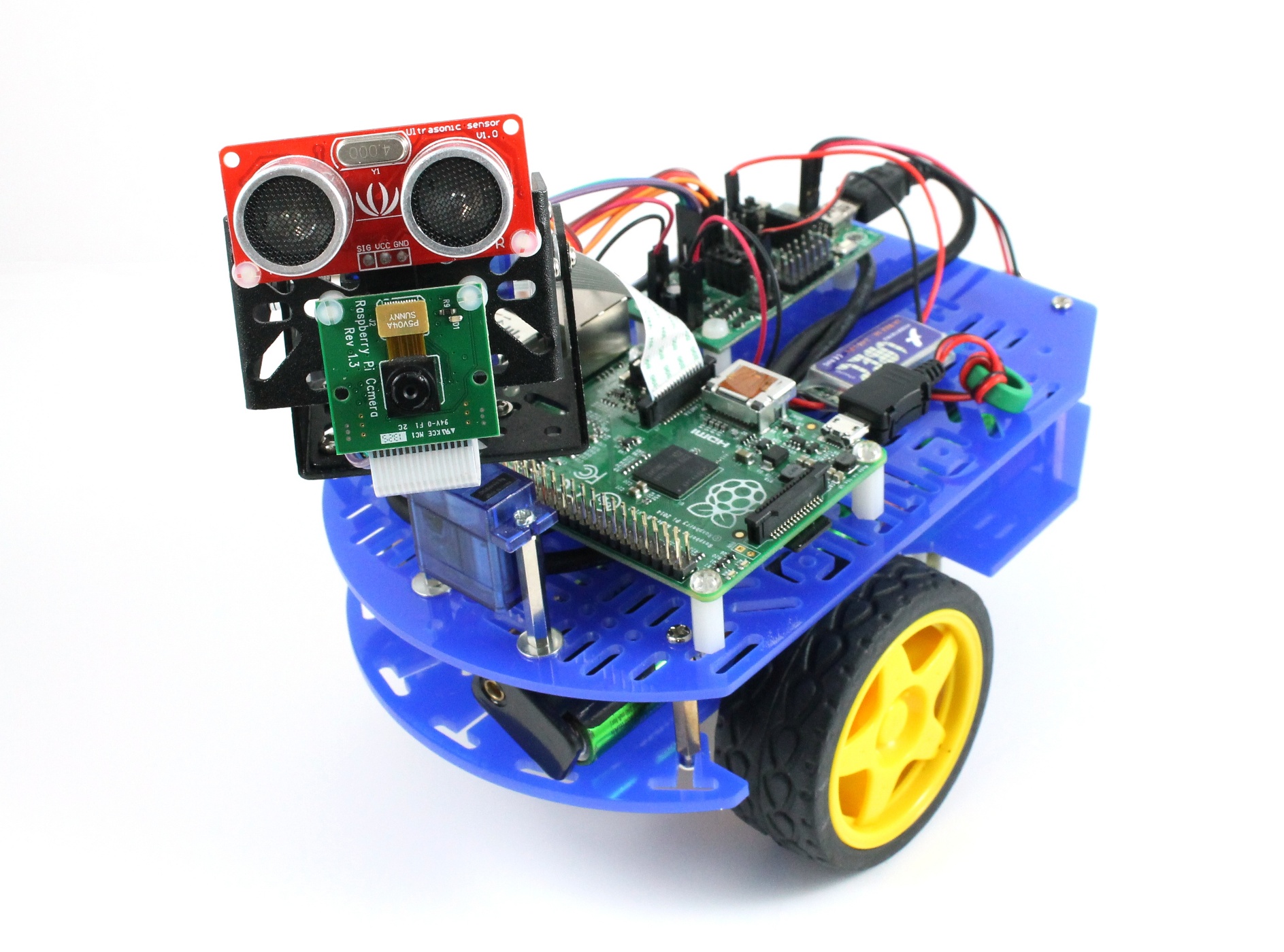
You can fit both a camera, and an ultrasonic sensor on the robot’s pan/tilt head.
In the image above we’ve attached an ultrasonic sensor to the pan/tilt head of the robot, and then connected it to the Mini Driver using a 3 pin jumper wire. The only pin you can attach the ultrasonic sensor to with our Mini Driver firmware is pin D12. Also, because reading from the ultrasonic sensor can take a long time, at the moment we only read from the ultrasonic sensor at a rate of 2Hz. If you need to attach more than one ultrasonic sensor to your robot, or if you need to read at a faster rate than 2Hz, then you’ll need to attach the other ultrasonic sensors to the Raspberry Pi’s GPIO pins.
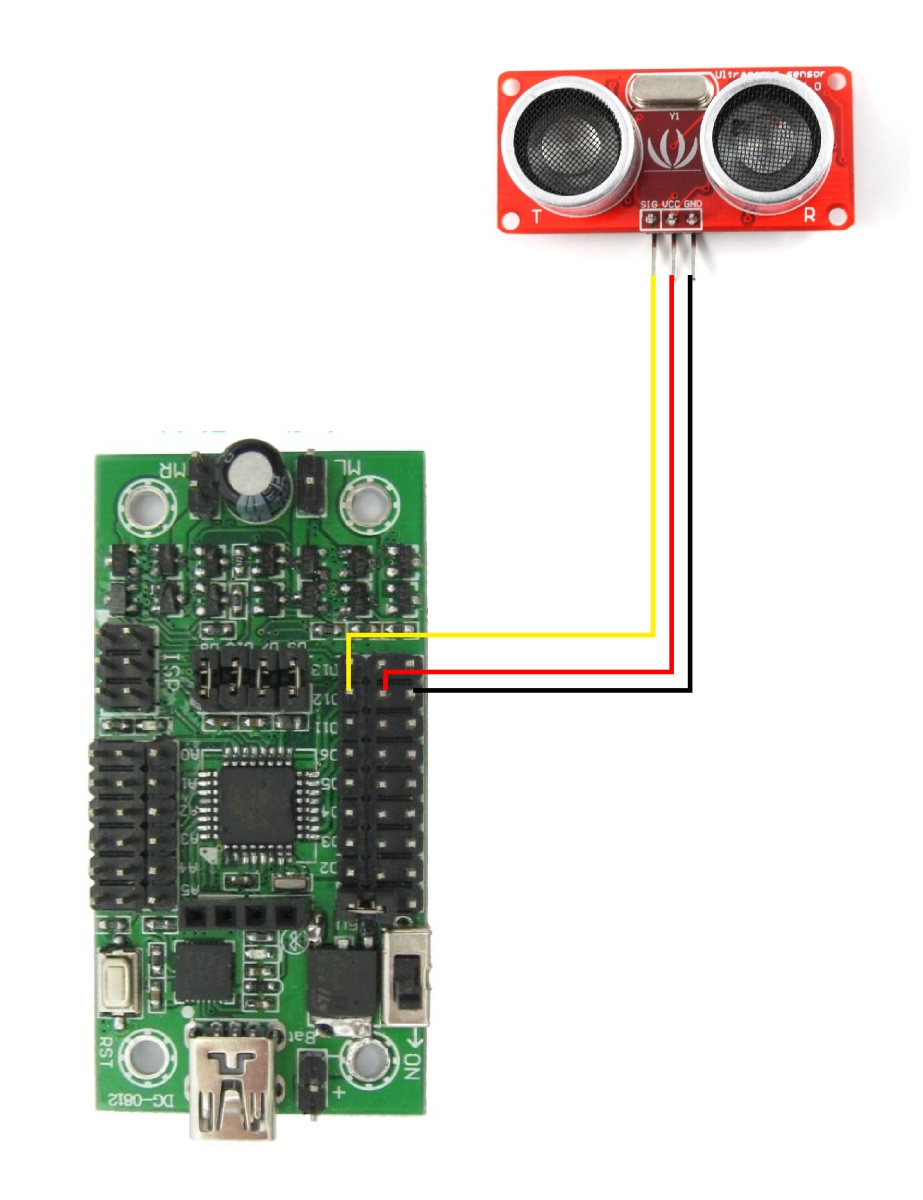
Connect the Ultrasonic sensor to D12
Analog
The analog inputs of the Mini Driver can be used to read from analog sensors where the output signal is between 0V and 5V. The ADC on the Mini Driver is a 10-bit ADC so the readings will be returned as values between 0 and 1023. In the image below we’ve connected the X, Y and Z channels of the ADXL335 accelerometer to pins A1, A2 and A3 of the Mini Driver. Accelerometers are great for detecting the acceleration due to gravity (and thus working out if the robot is on a slope), and they can also be used as a neat method for detecting collisions, as we showed in our blog post on ‘bump navigation‘.
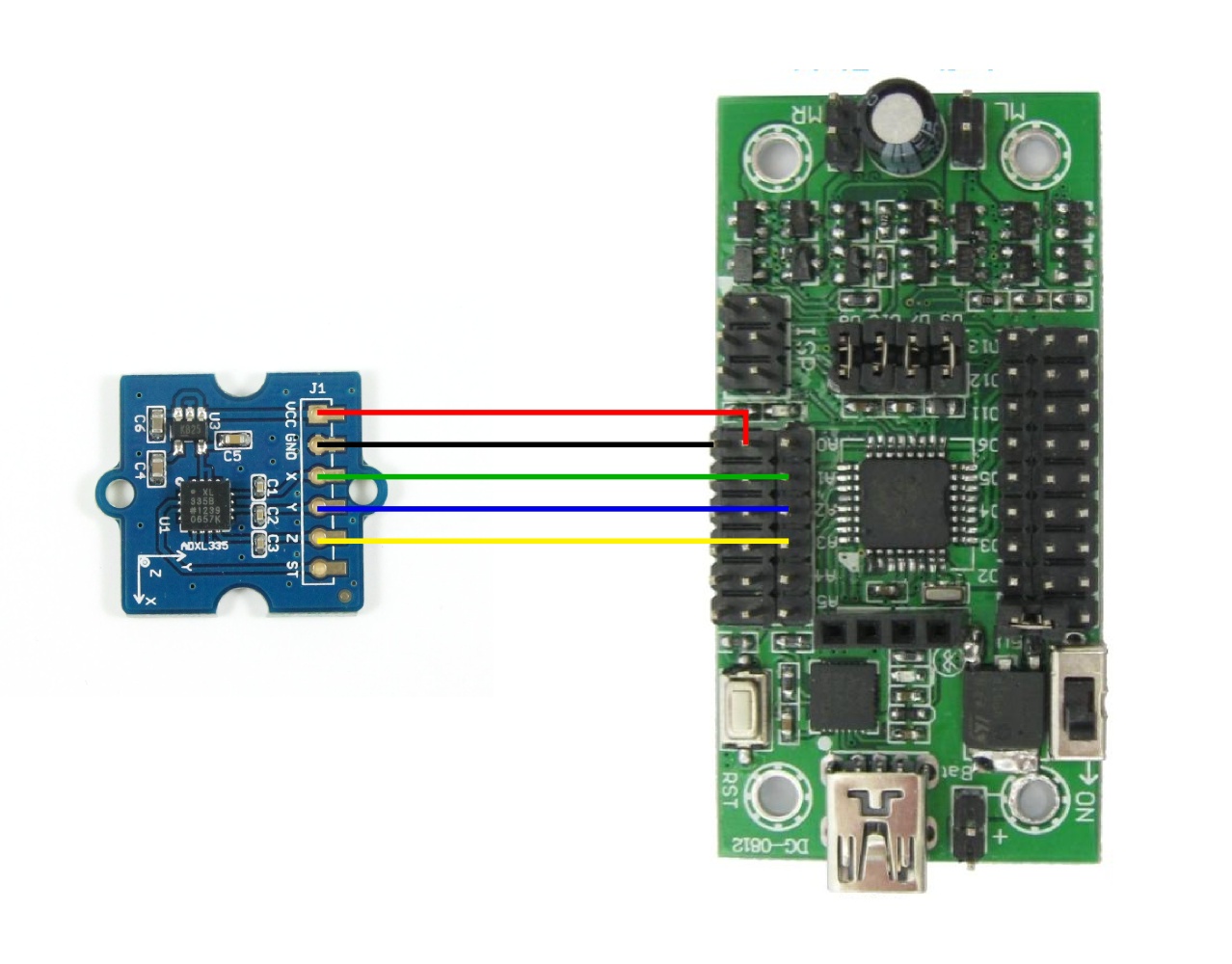
Attach analog sensors such as an ADXL335 accelerometer to the ADC input pins.
Incremental Encoders
Incremental Encoders are sensors which you can use to tell you how fast a motor is turning, and usually, what direction it’s turning in as well (see here for a good introductory article). We don’t yet sell encoders for the Dagu 2WD Chassis (coming soon), but in the meantime, you may still find this feature useful if you’re using a different chassis, which does have encoders, to build your robot.
Quadrature encoders have 2 outputs, phase A and phase B, and can be used to detect both the speed and direction in which the motor is turning. Wire the left encoder to pins D2 and D4, and wire the right encoder to pins D3 and D5. The Mini Driver firmware can also be made to work with single output encoders. In this case wire the left encoder to D2 and the right encoder to D3.
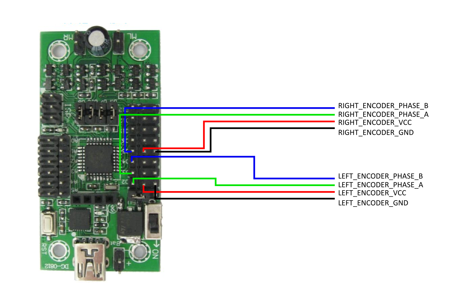
Connect the encoders up to the first 4 digital pins
Reading from the Sensors
Once you’ve connected up all your sensors, the next thing to think about, is how to read from the sensors, to make use of them in your control programs. The firmware on the Mini Driver (actually an Arduino sketch which can be found here) reads from the sensors at a rate of 100Hz and sends the data back to the Pi over the USB cable using serial.
On the Pi, you have two main options for talking to the Mini Driver. The first is to use the Mini_Driver Python class we provide in your own Python script, (example script here, read comments at top of file). The second, recommended and more flexible option, is to talk to the robot web server which is running on the Pi using the Python py_websockets_bot library.
Instructions for installing the py_websockets_bot library can be found in this blog post here. If you’ve already got py_websockets_bot installed then you may need to update it to get the latest version. This can be done by navigating to the py_websockets_bot library and running.
git pull
sudo python setup.py install
We’ve added an example script to py_websockets_bot called get_sensor_readings.py which shows you how to read sensor values from the robot. Run the script using the following command
examples/get_sensor_readings.py ROBOT_IP_ADDRESS
where ROBOT_IP_ADDRESS is the network address of your robot. After a short delay you should see sensor values streaming back from the robot.
Looking at the example script in more detail, the important bits of the script are as follows.
Configure the Sensors
Firstly we construct a SensorConfiguration object and send it over to the robot
# Configure the sensors on the robot
sensorConfiguration = py_websockets_bot.mini_driver.SensorConfiguration(
    configD12=py_websockets_bot.mini_driver.PIN_FUNC_ULTRASONIC_READ,
    configD13=py_websockets_bot.mini_driver.PIN_FUNC_DIGITAL_READ,
    configA0=py_websockets_bot.mini_driver.PIN_FUNC_ANALOG_READ,
    configA1=py_websockets_bot.mini_driver.PIN_FUNC_ANALOG_READ,
    configA2=py_websockets_bot.mini_driver.PIN_FUNC_ANALOG_READ,
    configA3=py_websockets_bot.mini_driver.PIN_FUNC_DIGITAL_READ,
    configA4=py_websockets_bot.mini_driver.PIN_FUNC_ANALOG_READ,
    configA5=py_websockets_bot.mini_driver.PIN_FUNC_ANALOG_READ,
    leftEncoderType=py_websockets_bot.mini_driver.ENCODER_TYPE_QUADRATURE,
    rightEncoderType=py_websockets_bot.mini_driver.ENCODER_TYPE_QUADRATURE )

# We set the sensor configuration by getting the current robot configuration
# and modifying it. In this way we don't trample on any other
# configuration settings
robot_config = bot.get_robot_config()
robot_config.miniDriverSensorConfiguration = sensorConfiguration

bot.set_robot_config( robot_config )
Pin D12 can be set as either PIN_FUNC_ULTRASONIC_READ or PIN_FUNC_DIGITAL_READ, pin D13 can be set as either PIN_FUNC_INACTIVE or PIN_FUNC_DIGITAL_READ, and the analog pins A0 to A5 can be set as either PIN_FUNC_ANALOG_READ or PIN_FUNC_DIGITAL_READ. The encoders can be set to be either ENCODER_TYPE_QUADRATURE or ENCODER_TYPE_SINGLE_OUTPUT.
Estimate Time Difference to Robot
For some robot applications, it can be important to know exactly when a sensor reading was made. In our software, whenever a sensor reading reaches the Raspberry Pi, it is timestamped with the time that it arrived at the Pi. The problem is however, that if your robot control script is running on a PC connected to the robot over a network, then the system clock of the control PC is likely to be different from the system clock of the Pi. To resolve this problem, we provide a routine to estimate the offset from the system clock to the Raspberry Pi’s clock.
robot_time_offset = bot.estimate_robot_time_offset()
At the moment the algorithm for estimating the time offset is not particularly efficient, and will block for about 10 seconds or so. In the future we’d like to modify this routine so that it estimates the time offset asynchronously and continuously in the background. In the meantime, if you’re not interested in the precise time at which sensor readings were made, then you can leave this line out of your own programs.
Read the Status Dictionary
Sensor readings are returned as part of the status dictionary which, as you might expect, contains data about the current status of the robot. Retrieve the status dictionary using the following line
status_dict, read_time = bot.get_robot_status_dict()
Read the Sensor Values
Having obtained the status dictionary, the sensor readings are returned as a dictionary called ‘sensors’. Each sensor reading is represented as a timestamp which gives the time on the Pi system clock when the reading arrived at the Pi, coupled with the data for the sensor reading.
# Print out each sensor reading in turn
sensor_dict = status_dict[ "sensors" ]
for sensor_name in sensor_dict:

    # Get the timestamp and data for the reading
    timestamp = sensor_dict[ sensor_name ][ "timestamp" ]
    data = sensor_dict[ sensor_name ][ "data" ]

    # Calculate the age of the reading
    reading_age = (time.time() + robot_time_offset) - timestamp

    # Print out information about the reading
    print sensor_name, ":", data, "reading age :", reading_age
The format of the data entry will depend on the type of sensor being read. For the sensor types that can be attached to the Mini Driver the dictionary entries are
- batteryVoltage – This is a floating point number giving the current voltage of the batteries attached to the +/- pins of the Mini Driver.
- ultrasonic – This is an integer giving the distance reading in centimetres. The maximum range of the sensor is 400cm, and if it looks as if no ultrasonic sensor is attached to the Mini Driver then the value returned will be 1000.
- analog – This is an array of 6 integers, one for each of the analog pins A0 to A5, giving a value from 0 to 1023, representing 0V to 5V. If an analog pin is configured as a digital input then it will still have an entry in this array, but it will be set to 0.
- digital – This is a byte, with each bit representing one of the possible digital pins. Looking at the byte from left to right, the bits correspond to pins A5, A4, A3, A2, A1, A0, D13 and D12.
- encoders – This is a pair of integers giving the current tick count for the left encoder and the right encoder.
Connecting Sensors to the Raspberry Pi
You should now have a good idea of how to connect a variety of sensors to your robot, and how to read values from those sensors using the py_websockets_bot library. You may find however, that you also need to connect some sensors to the Raspberry Pi’s GPIO pins. This could be because you run out of space on the Mini Driver (the more sensors the better!) or because you have a sensor that uses I2C or SPI as a means to communicate with them.
As an example, in the images below we’ve attached a digital light sensor, and a digital compass to the I2C GPIO pins of the Pi using some jumper wires and a Grove I2C hub, to create a robot that can navigate with the compass, and detect light levels (perhaps it wants to hide in dark places…).
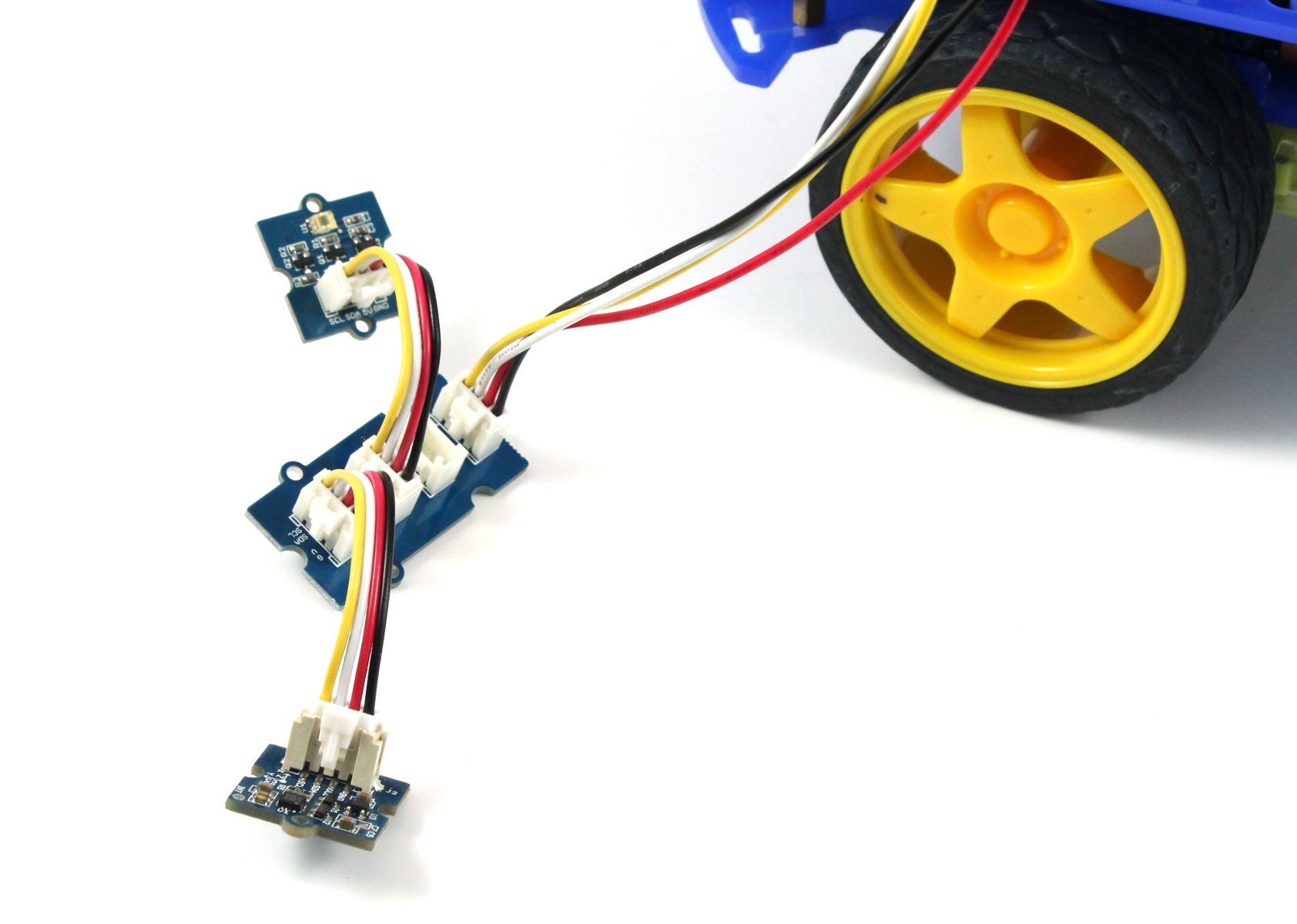
You can attach a range of sensors (such as a digital light sensor and a compass) using I2C
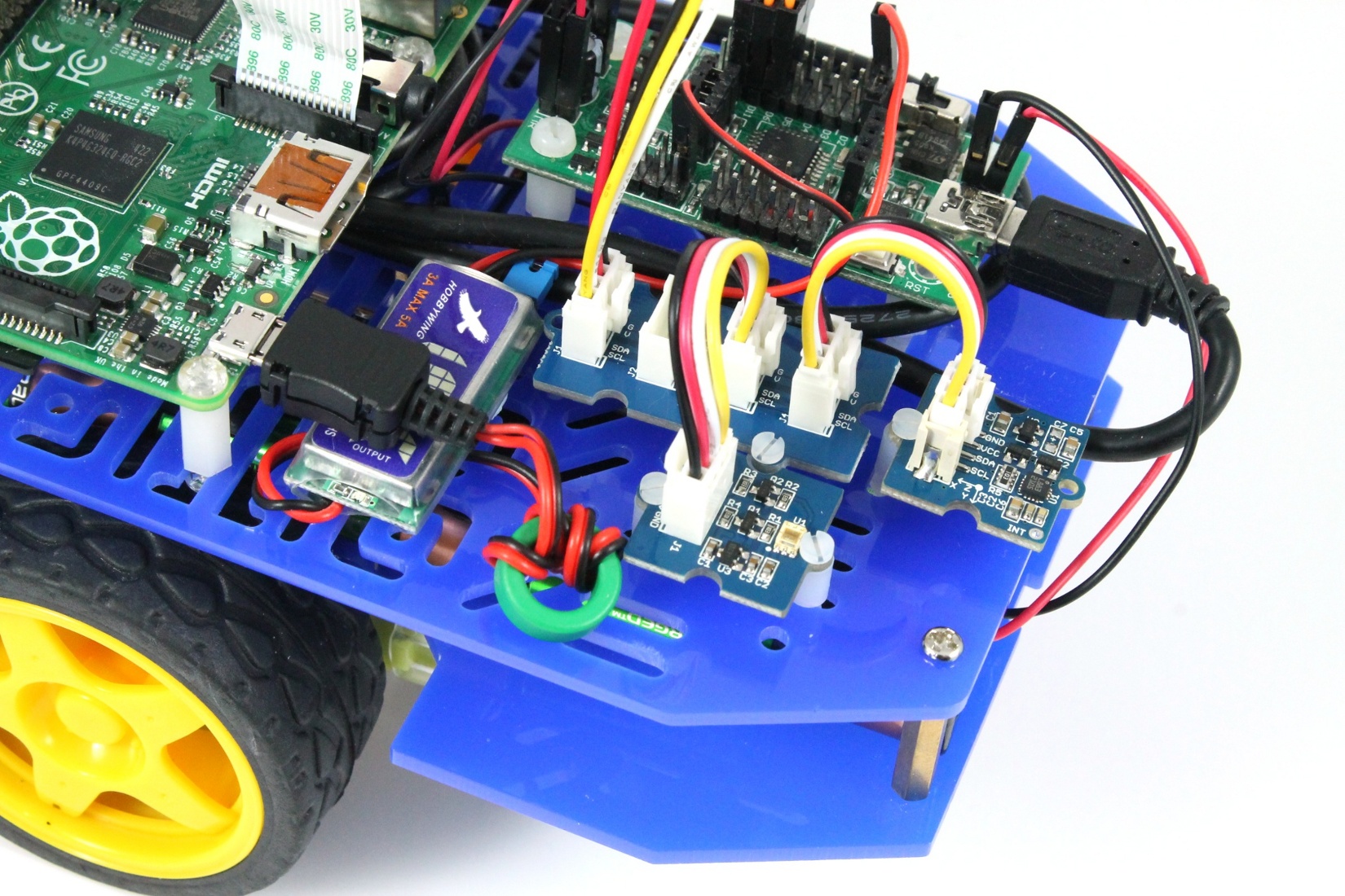
The sensors fixed to the robot
We don’t have the space here to go into detail about how you would wire up all the different sensor types to the Pi’s GPIO pins, and then communicate with them using Python. But there are lots of good tutorials on attaching sensors to the Pi that you can find with Google. Once you’re in the situation where you can connect to, and communicate with the sensor, the steps you need to take to integrate it with the robot are
- Take a copy of default_sensor_reader.py and rename it to something like ‘my_sensor_reader.py’. Leave it in the sensors directory.
- Fill in the routines in the file. The comments in the file should tell you what you need to do, basically you need to provide a routine to set up your sensors, to read from your sensors and optionally to shut them down. When you read from the sensors you’ll create a SensorReading object (timestamp and data) and put it into a dictionary for integration with the main sensor dictionary. Note: Do not change the name of the class from PiSensorReader.
- Update the robot configuration to use your sensor reader module. This can be done with code that looks like this
robot_config = bot.get_robot_config()
robot_config.piSensorModuleName = "sensors.my_sensor_reader"
bot.set_robot_config( robot_config )
If all goes well then your sensor readings should now be returned to you in the sensor dictionary.
Taking Things Further
This tutorial has shown some of the many different types of sensor you can attach to your Raspberry Pi robot, and hopefully it’s given you a good idea of how you’d go about wiring them up and reading from them. Now, the sky is the limit, as putting sensors onto your robot really makes it much easier to program interesting and intelligent behaviours for your robot. Build a robot that can drive around a room, avoiding obstacles, use a light sensor to get the robot to chase bright lights etc, the possibilities are endless.
If you have any questions about attaching sensors to your robot, or need clarification on anything we’ve talked about in this tutorial, then please post a comment below or in our forums. Also we’d love to hear what sensors you decide to put on your robot, and how you end up using them. ![]()
Could you make it a pdf so that you can open the page in schools as this is filter as it is a blog
Hi Ryan,
Ah, that’s good to know, I didn’t realise that blog sites were filtered by some networks.
I’ll look at adding in a dedicated PDF download option, but for now, you should be able to get reasonable results by selecting ‘Print’ from the File menu and then using one of the available options for printing to a file. On Linux, and also I believe Macs there is a print to PDF option which works well. On Windows there should be a Microsoft XPS Document Writer option. I’ve not used XPS files in the past, but it worked well when I tried it on Windows 7, and I assume that an XPS viewer is provided on most versions of Windows. Alternatively this tutorial shows you how to add a print to PDF option to Windows for free.
Please let me know how you get on with this, if you have major problems then I can post PDF versions manually. Also, just out of interest, can you access this readthedocs site on your school network? We’re planning to create a definitive manual at some point using this site as it also provides the option to download as PDF, so it would be good to know if it’s visible.
Regards
Alan
The read the docs site does work